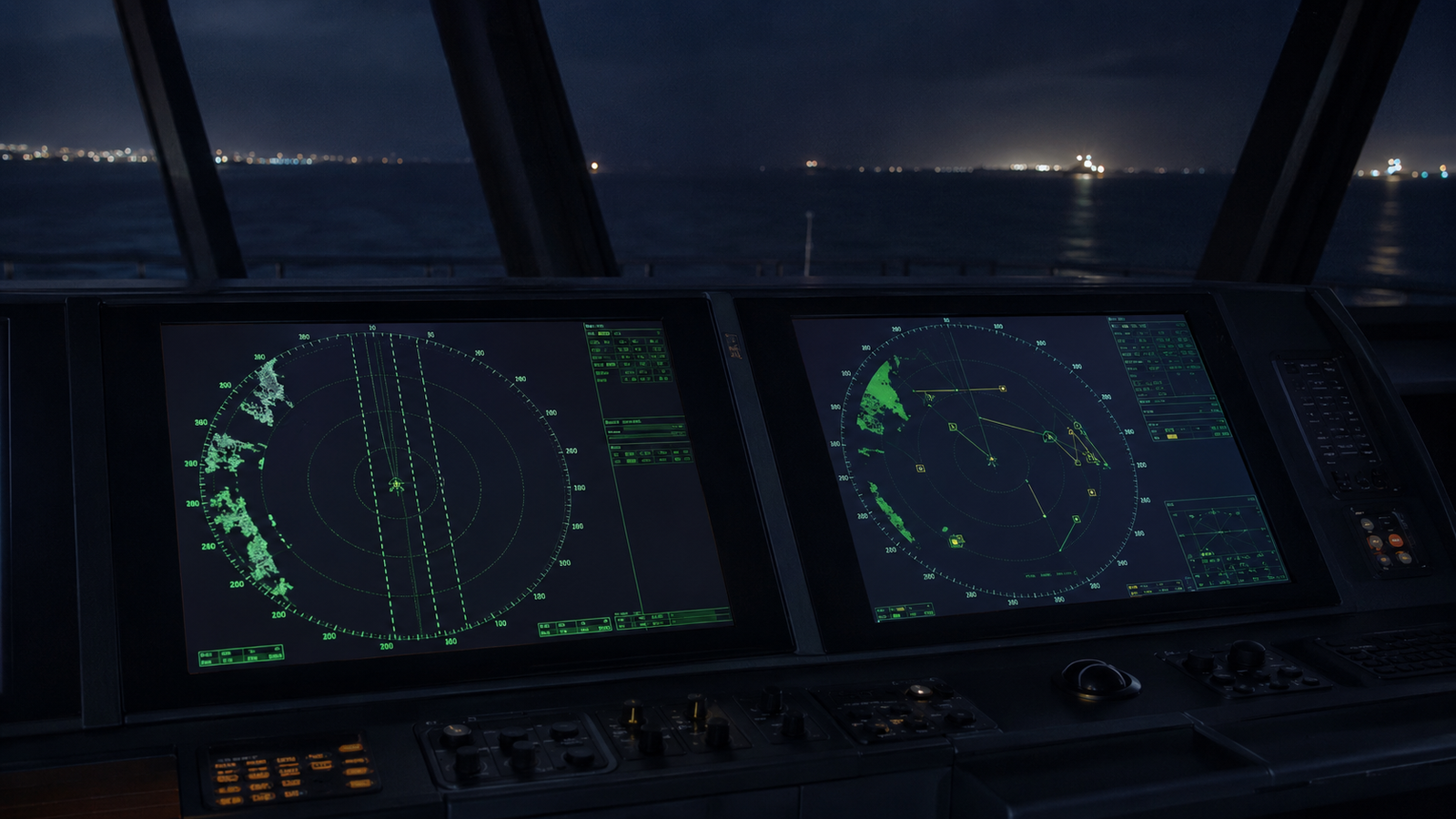
When I open a VDR review, the radar screenshots are among the first things I examine. Not to confirm that the radar was switched on — that is rarely the issue — but to understand how it was being used. What the mode indicators show. Whether radar position fixing — ranges and bearings from positively identified fixed objects — has any presence in the watch at all. Whether parallel indexing lines are visible on the display. Whether the Target plots are From ARPA or AIS.
The radar being on and the radar being used correctly are two different things. The VDR distinguishes between them.
The radar being on and the radar being used correctly are two different things. The VDR distinguishes between them.
Stabilisation Mode: The Setting That Determines Whether ARPA Can Be Trusted
Of all the radar settings the VDR exposes, stabilisation mode is the one with the most direct consequence for collision avoidance — and the one most frequently found to be incorrect on the collision avoidance radar.
BPG Section 5.11.7 is explicit: for collision avoidance purposes, speed and heading inputs should be sea stabilised — water track — providing ARPA with speed and course through the water. The same section uses the word hazardous to describe using ARPA in ground stabilised mode for assessing risk of collision where currents or tides are present.
The technical reason matters. Ground stabilisation takes speed input from GNSS — speed over ground. In waters with set and drift, this causes ARPA to misrepresent the true aspect of approaching targets. A vessel on a collision course may generate vectors suggesting it will pass clear. The error is invisible to an officer who does not understand what the stabilisation mode is doing to the ARPA calculation underneath.
MGN 379 §3.6.1 sets out the distinction clearly
Sea Stabilisation
Speed and heading from gyro and log
Speed and course through the water
True aspect of target accurately determined
Best suited for anti-collision work
Ground Stabilisation
Speed and heading from GNSS
Speed and course over ground
Difficulty determining true aspect of target
Best suited for coastal navigation and track monitoring
Ground stabilisation has legitimate uses — monitoring own ship’s set and drift, track prediction in channelled waters. The issue is not the mode itself. The issue is that the radar designated for collision avoidance decisions must be sea stabilised. Where two radars are fitted, MGN 379 §3.3 recommends designating one for anti-collision and one for navigation, particularly in congested or shallow waters. The VDR shows whether that designation exists in practice — and whether the correct stabilisation mode was applied to each.
Display Orientation: Why North-Up Makes the Most Sense
Of the three orientation modes available — North-up, Course-up, and Head-up — North-up is the preferred choice for coastal navigation and port approaches, and the VDR consistently supports this finding when comparing ships where position fixing is well executed against those where it is not.
The reason is practical rather than regulatory. North-up orients the radar picture to match the ECDIS display and the paper chart. A navigator moving between radar and ECDIS during a coastal passage is working from the same mental picture on both screens. Ranges and bearings taken from the radar translate directly to the chart without a mental correction for orientation. When position fixing involves comparing radar ranges against charted objects, the cognitive load of doing this on a North-up radar is significantly lower than on a Course-up or Head-up display.
MGN 379 §3.6.4 notes that Course-up may be preferred during collision avoidance because the display matches what the navigator sees visually ahead — a valid point. The practical approach on a two-radar bridge is North-up on the navigation radar and Course-up on the collision avoidance radar, each set to match its designated function. What the VDR finds more often is neither — both radars in the same orientation regardless of their designated role, often unchanged from departure to arrival.
Parallel Indexing: On the Passage Plan, Off the Radar
This is one of the most consistent findings across remote navigational audits. The passage plan has parallel index lines correctly marked. The ECDIS has them correctly entered. The radar has nothing.
BPG 5.11.10 and MGN 379 §3.8 are both clear on what parallel indexing provides: continuous monitoring of cross-track distance without dependence on GNSS. An index line drawn parallel to the planned track at the desired passing distance from a fixed object gives the OOW an immediate, real-time indication of whether the ship is maintaining its intended track. No position fix required. No ECDIS interrogation. The echo moving along the line tells the story.
The technique works in both relative motion and sea stabilised true motion, using a stabilised display. It requires nothing more than familiarity with the radar’s index line function and a correctly set up display.
What the VDR typically shows is the parallel index correctly planned and absent from execution. The ECDIS cross-track distance indicator is being monitored instead. This is not wrong — but it is a different tool with a different dependency chain. If GNSS is degraded or spoofed, the ECDIS XTD is compromised. The parallel index is not, because it works from a fixed radar echo, not a satellite-derived position.
MGN 379 §3.8 makes this explicit: parallel indexing should be practised in clear weather during straightforward coastal passages so that watchkeepers remain familiar with the technique for use in more demanding conditions — restricted visibility, GNSS denial, confined waters. The VDR review of a straightforward coastal passage is an accurate indicator of whether that familiarity exists.
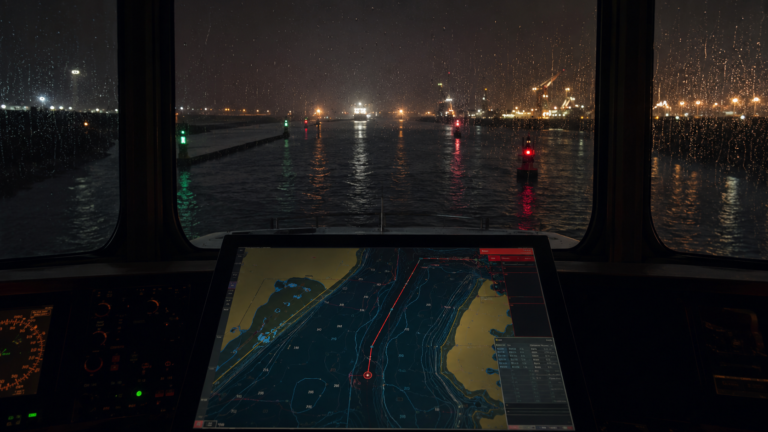
The passage plan is the intention. The radar display is the execution. The VDR shows both — and the gap between them
Radar Position Fixing: Why Ranges and Bearings Are Not Optional
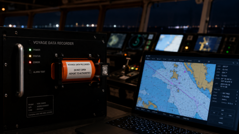
The VDR captures ECDIS screenshots alongside radar screenshots. When I compare the two during a coastal passage, I am looking for evidence that radar position fixing — ranges and bearings from identified fixed objects — was supporting the ECDIS position, not simply accepted from the GNSS feed without independent verification.
What I find frequently is manual position fixes placed on the ECDIS using the chart’s own reference — bearing and range pulled from the chart geometry rather than observed from the radar. This satisfies the logbook entry. It does not satisfy the purpose of position fixing, which is to verify where the ship actually is using an independent observation.
MGN 379 §3.7 lists what should be considered when using radar for position monitoring: identity of fixed objects, radar performance, heading marker alignment, VRM and EBL accuracy, and correct setting of parallel index lines. These are active checks, not passive readings. A position fix using a radar range and EBL bearing from a positively identified fixed object is an independent verification of the GNSS-derived position. An ECDIS position fix placed by moving a cursor is not.
BPG 5.11.5 notes that accurate speed and heading inputs are essential for target tracking accuracy. The same principle applies to position fixing — the radar is only as useful for this purpose as the care taken to use it correctly. This is increasingly relevant given the growth of GPS spoofing incidents in high-risk areas. A ship with a correctly used radar, taking regular ranges and bearings from fixed objects, will detect a spoofed position before it becomes a grounding. A ship relying entirely on ECDIS will not.
Over-Reliance on ECDIS: What the VDR Sees
MGN 379’s opening section cites over-reliance on a single electronic navigational aid as a primary cause in multiple accidents. ECDIS is the most capable navigation tool on the bridge. It is also the most dependent on the integrity of its inputs — primarily GNSS.
The VDR regularly shows a bridge operating with ECDIS as the sole active navigation reference, radar running in the background with no ARPA targets plotted, no parallel index lines set, and no radar ranges being taken for position verification. The radar is on. It is doing nothing.
BPG 5.11.2 states clearly that radar is the main electronic collision avoidance tool for bridge watchkeepers and supports effective passage plan monitoring. It is not a backup for when ECDIS fails. It is a concurrent, independent system that should be actively used throughout any coastal or pilotage passage.
The practical standard is straightforward: ECDIS for route monitoring and passage management, radar for collision avoidance and independent position verification. The two systems checking each other, not one doing the work of both.
Where radar position fixing is absent from the VDR record, the ship was navigating on a single source. That is the definition of over-reliance.
AIS on the Radar Display: Situational Awareness, Not Collision Avoidance
One further finding the VDR surfaces regularly — through a combination of radar screenshots and bridge audio — is the use of AIS-derived CPA and TCPA values for collision avoidance decisions, rather than ARPA-tracked values.
Modern radars display AIS target information alongside or merged with ARPA data. BPG 5.11.9 requires the radar display to clearly indicate whether target information comes from ARPA or AIS. The same section is unambiguous: AIS information, particularly CPA and TCPA, should not be relied on for collision avoidance. MGN 379 §3.3 repeats this — AIS may be used for situational awareness but not for collision avoidance decisions.
The reason is technical. AIS transmits course and speed over ground. In waters with tidal influence, this produces an inaccurate aspect of the target relative to what the ARPA — using speed through the water — would generate. An officer reading AIS CPA values on a radar that is also ground stabilised is compounding two separate sources of error in the same collision avoidance assessment.
The VDR establishes which data source was in use. Where the radar screenshots show AIS Max Target selected rather than ARPA, and bridge audio shows CPA discussions based on AIS readouts, the finding is clear.
What the VDR Captures — and What SIRE 2.0 Will Examine
SIRE 2.0 Section 3.2.4 provides for unannounced remote navigational assessments using VDR data, specifically focused on high-risk passages such as pilotage and high-traffic-density straits. The radar screenshots captured during those passages — mode indicators, ARPA target count, parallel index lines, position fix method — are visible in playback and form part of that assessment.
An inspector examining VDR data will be asking the same questions I ask on every review: Was the collision avoidance radar sea stabilised? Were parallel index lines in use? Were position fixes supported by radar observations? Was ARPA or AIS providing the CPA values being relied upon?
The answers are in the screenshots. They always have been.
→ Explore our VDR Navigational Audit Service — View Service Page
VDR Navigational Audits: What They Are, Why They Matter, and When to Do One
How a VDR Navigational Audit Works — A Step-by-Step Guide for Ship Managers
The First VDR Audit Your Fleet Runs Should Be Announced. Here’s Why.
When VDR Data Works For You, Not Against You
The Anchor Is Down. The VDR Doesn’t Know That.
The Port Approach Is Already on Film. Most Managers Don’t Know It.
The Master Pilot Exchange: What the VDR Hears, and What Most Ships Leave Unsaid